Printed circuit boards are the backbone of modern electronic devices. From consumer electronics to industrial machines and automotive systems, PCBs provide the pathways that connect electronic components and allow devices to operate correctly. However, like any electronic system, circuit boards can experience faults due to design issues, manufacturing defects, or environmental factors. PCB Troubleshooting is the process of identifying, diagnosing, and resolving these issues to restore the board’s functionality and ensure reliable performance.
Understanding the common problems that occur in PCBs and knowing how to detect them can significantly reduce downtime, improve product reliability, and extend the life of electronic equipment.
What Is PCB Troubleshooting?
PCB Troubleshooting refers to the systematic process of identifying faults in a printed circuit board and determining the root cause of the malfunction. It involves inspecting the board, testing electrical connections, analyzing component performance, and correcting defects that prevent the circuit from functioning properly.
Troubleshooting can be performed during different stages of a PCB’s lifecycle. It may occur during the manufacturing stage, where engineers check for assembly or soldering errors, or after the board has been deployed in a device and begins to show signs of malfunction.
The goal of troubleshooting is not only to fix the immediate problem but also to prevent similar issues from occurring in future designs or production runs.
Common PCB Problems
Many electronic failures originate from issues within the printed circuit board. During PCB Troubleshooting, technicians often encounter problems such as short circuits, open circuits, component failures, and solder joint defects.
Short circuits occur when two conductive traces unintentionally connect, allowing electricity to flow through an unintended path. This can cause overheating, component damage, or total system failure.
Open circuits are another common issue. They occur when a connection in the circuit path is broken, preventing electrical signals from reaching certain components. This type of fault often results in devices that do not power on or fail to perform specific functions.
Component failures can also lead to PCB malfunction. Electronic parts such as resistors, capacitors, and integrated circuits may become damaged due to electrical overload, heat, or manufacturing defects.
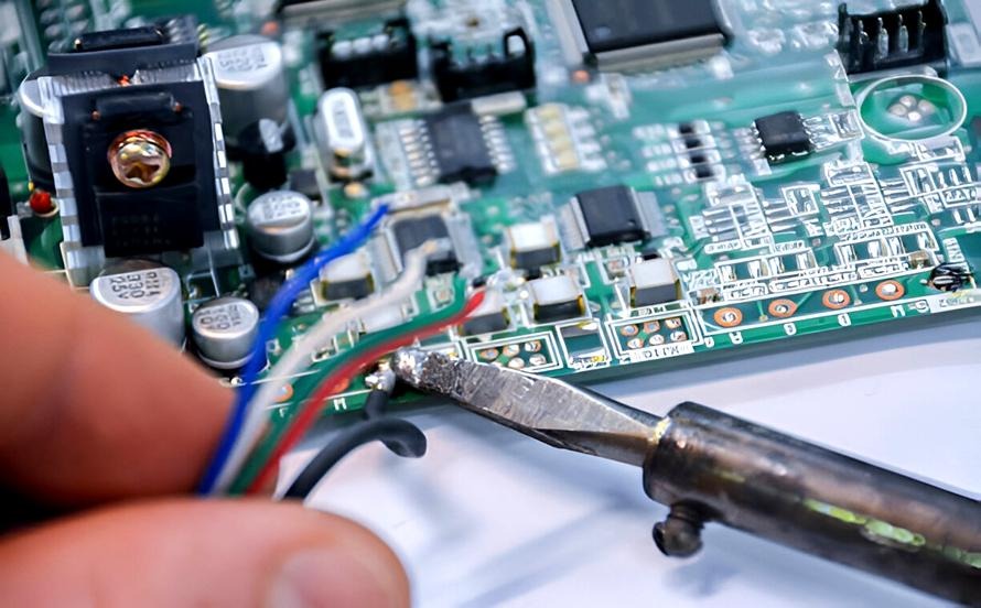
Soldering problems are also frequently discovered during troubleshooting. Poor solder joints, insufficient solder, or solder bridges can disrupt electrical connections and affect circuit performance.
Causes of PCB Failures
Several factors can contribute to the need for PCB Troubleshooting. One of the most common causes is design errors. If the PCB layout is not properly optimized, traces may be too close together, components may be poorly placed, or power distribution may be inadequate. These issues can create electrical interference or overheating.
Manufacturing defects are another major cause of PCB problems. Improper etching, misaligned drilling, or low-quality materials can weaken the board structure or interrupt electrical pathways.
Environmental conditions can also affect PCB performance. Excessive heat, humidity, dust, and vibration can degrade solder joints and components over time. In industrial environments, exposure to chemicals or mechanical stress can further increase the risk of board failure.
Electrical overstress is another common factor. Power surges, incorrect voltage levels, or poor grounding can damage sensitive electronic components and lead to circuit failure.
Tools Used in PCB Troubleshooting
Effective PCB Troubleshooting requires the use of specialized tools that help engineers analyze circuits and detect faults accurately. One of the most commonly used tools is a digital multimeter. This device measures voltage, current, and resistance, allowing technicians to verify whether circuits are functioning correctly.
Oscilloscopes are also widely used during troubleshooting. These instruments allow engineers to observe electrical signals and analyze waveform patterns. By examining signal behavior, they can identify issues such as noise, distortion, or timing errors.
Thermal cameras are sometimes used to detect overheating components. Excess heat often indicates electrical problems such as short circuits or excessive current flow.
Magnification tools such as microscopes or inspection cameras are also essential. They help technicians identify small defects such as cracked solder joints, damaged traces, or improperly placed components.
Automated optical inspection systems may also be used in manufacturing environments to detect assembly errors before the board reaches the final testing stage.
PCB Troubleshooting Process
A structured approach is essential for effective PCB Troubleshooting. The process typically begins with visual inspection. Engineers carefully examine the board for visible damage such as burned components, broken traces, or loose connections.
The next step involves checking the power supply. Many circuit failures occur because the board is not receiving the correct voltage or current. Verifying the power input ensures that the board is properly energized.
After confirming the power supply, technicians test different sections of the circuit using measurement tools. By comparing the measured values with the expected values in the circuit design, they can narrow down the location of the fault.
Signal tracing is another important step in the troubleshooting process. Engineers follow the signal path through the circuit to determine where the signal stops or becomes distorted.
Once the faulty component or connection is identified, repairs can be made. This may involve replacing damaged components, repairing traces, or reworking solder joints.
Finally, the board undergoes testing to ensure that the repair has restored normal operation.
Preventing PCB Issues
While PCB Troubleshooting helps resolve problems after they occur, prevention is always the better approach. Careful design practices can significantly reduce the risk of PCB failures.
Designers should ensure proper spacing between traces, optimize component placement, and include adequate thermal management features. Good grounding and power distribution are also critical for stable circuit operation.
Using high-quality materials and reliable manufacturing processes also plays an important role in preventing issues. Strict quality control during production can detect defects early and reduce the likelihood of faulty boards reaching the market.
Regular maintenance and proper environmental protection can further extend the lifespan of electronic systems that rely on PCBs.
Conclusion
PCB Troubleshooting is a critical process for maintaining the performance and reliability of electronic devices. By systematically identifying and resolving circuit faults, engineers can restore functionality and prevent long-term damage to electronic systems. Understanding common PCB issues, using the right diagnostic tools, and following a structured troubleshooting process can greatly improve the efficiency of repairs and reduce downtime.
In addition to effective troubleshooting practices, working with an experienced PCB manufacturer in Germany or other reputable manufacturing partners can help ensure high-quality circuit boards that minimize the risk of defects and deliver reliable performance in demanding applications.